


Before opening, de-energize the base and secure it against being re-energized.
Disconnect any external voltages connected to the unit and secure it against accidental re-energization.
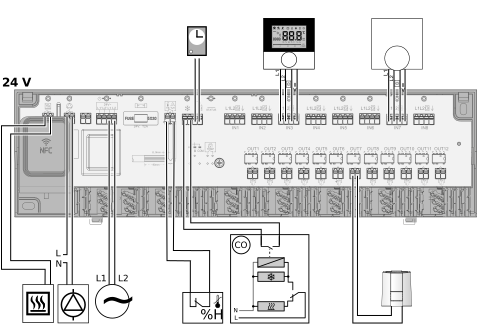
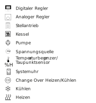
For the connection of the power supply, the cable cross-sections must be 0.75 mm² – 1.5 mm² for 24 V or 1.5 mm² for 230 V. Depending on the voltage version of the base, it is possible to take L1 and L2, or L and N, as well as the protective conductor, from the base. A temperature limiter/dew point sensor can be connected to the TB/%H contact. If this contact is not used, it must be bridged (provided for at the factory). The bridge must be removed when a connection is established at contact is TB/%H. The temperature limiter/dew point sensor must be designed as a normally closed contact.
The activation of the special functions as well as the setting of “Disable cooling” and the assignment of the inputs to the outputs can only be set via the app. The external system clock transmits the input signal to the connected thermostats.
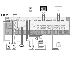
The 24 V version of the base station must have a voltage supply via a safety transformer in accordance with EN 61558-2-6 or a Class II transformer in accordance with UL for North America.
The following parameters can be set via the app:
| Switch-on delay of the pump | default: 2 minutes |
| Pump follow-up time | default: 2 minutes |
| Switch-on delay of the boiler | default: 0 minutes |
| Nachlaufzeit Boiler | default: 0 minutes |
| Maximum inactive time of the pump before the pump protection function starts | default: 3 days |
| Activation time of the pump (pump protection function) | default: 5 minutes |
| Maximum inactive time of the valve before the valve protection function starts | default: 16 days |
| Valve actuation time (valve protection function) | default: 5 minutes |

A room controller can be assigned to each actuator. Options in the app:
- Adjustment of the listed factory settings
- Assignment of names for the corresponding rooms
| Actuators | Room thermostat |
| 1 + 2 | 1 |
| 3 + 4 | 2 |
| 5 + 6 | 3 |
| 7 + 8 | 4 |
| 9 | 5 |
| 10 | 6 |
| 11 | 7 |
| 12 | 8 |