

Warning! Electrical voltage! Danger to life!
Before opening, de-energize the base and secure it against being re-energized.
Disconnect any external voltages connected to the unit and secure it against accidental re-energization.

Controllers with a TRIAC switching element that generate a leakage current at the output are not compatible with this system.
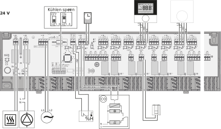
To connect the power supply, the cable cross-sections must be 0.75 mm² – 1.5 mm² for 24 V or 1.5 mm² for 230 V. Depending on the voltage version of the base unit, it is possible to tap L1 and L2 or L and N, as well as the ground wire, via the base unit. A temperature limiter/dew point sensor can be connected to the TB/%H terminal. If this terminal is not used, it must be jumpered (provided by the manufacturer). As soon as a connection is made to the TB/%H terminal, the jumper must be removed. The temperature limiter/dew point sensor must be designed as a normally closed contact. DIP switches 1–8 “Lock out cooling” are set to “Off” at the factory. Setting them to “On” locks out cooling for every HZ for “
.”
For systems that are operated in cooling mode, the “Block cooling” function must be set to ON on all unoccupied heating zones using the DIP switch. If the DIP switch is set to OFF, the corresponding output is not switched off and the pump and boiler contacts remain activated. The external system clock transmits the input signal to the connected thermostats.

The 24 V version of the base must be supplied via a safety transformer in accordance with EN 61558-2-6 or a Class II transformer in accordance with UL for North America.