
Skip to content
Logo
  • English
    • German

Alpha direct Balance base station

  • Intended use
  • Device overview
  • Montage
  • Electric connection
  • LED signaling
  • Commissioning mode
  • Automated hydraulic balancing
  • Maintenance
  • Disassembly
  • Hydraulic balancing remains necessary
  • Automatic heat distribution
  • Flow limiter not required
  • Cross-distribution network balancing required
  • Base station learning phase
  • Calibration
  • Compatibility
  • Cooling application
  • Switching between heating and cooling
  • Boiler control system
  • Bypassing heating zones
  • Valve protection

Alpha direct downloads

  • Alpha direct Balance Downloads
  • Alpha direct Balance Switch / Balance Switch Modbus downloads
  • TÜV certificates
  • Alpha direct Thermostat 55 Matrix downloads

Balance NFC app

  • Requirements for using NFC
  • Privacy policy
  • App functions
  • Download the app

Alpha direct thermostat 55 Matrix

  • Connection diagram / port overview
  • Function »Heating– Cooling«
  • Setting the corresponding parameters
  • Setting the target temperature
  • Operating lock
  • Set display to standby mode
  • Switching the device on / off
  • RMO (operating mode)
  • BOS (Boost)
  • PRG (heating program)
  • Setting up heating programs
  • VAT (Temperature holiday mode)
  • BRW / BRS (Display brightness)
  • NET (Set up WiFi)
  • DAT (date, time)
  • SWT (summer time / winter time)
  • INS (Installer)
  • CMO (control algorithm)
  • WEH (type of heating)
  • SMO (sensor mode)
  • DIF (Hysteresis)
  • ADP (Smart Start)
  • FLT (Temperature limiter floor sensor)
  • VAL (operating principle)
  • VPA / VPD (Valve protection)
  • TSS (temperature unit)
  • WMO (manual heating / cooling)
  • CAR / CAF / CAE (calibration)
  • ALO / AHI (setpoint limiter)
  • FLO / FHI (setpoint limiter)
  • ELO / EHI (setpoint limiter)
  • ANT (time automatically)
  • COL (block cooling)
  • FAC (factory reset)
  • ESC (exit)
  • Alpha smart app

Automated hydraulic balancing

  • How it works
  • A practical guide for technicians: Hydraulic balancing using automated systems
  • Applying for government grants
  • TÜV certificates

Alpha direct Balance Switch base station

  • Intended use
  • Device overview
  • Montage
  • Electric connection
  • LED signaling
  • Commissioning mode
  • Automated hydraulic balancing
  • Maintenance
  • Disassembly
  • Balance NFC app
  • Hydraulic balancing remains necessary
  • Automatic heat distribution
  • Flow limiter not required
  • Cross-distribution network balancing required
  • Base station learning phase
  • Calibration
  • Compatibility
  • Cooling application
  • Switching between heating and cooling
  • Boiler control system
  • Bypassing heating zones
  • Valve protection

Alpha direct Balance Switch Modbus base station

  • Intended use
  • Device overview
  • Montage
  • Electric connection
  • LED signaling
  • Commissioning mode
  • Automated hydraulic balancing
  • Register description
  • Maintenance
  • Disassembly
  • Balance NFC app
  • Hydraulic balancing remains necessary
  • Automatic heat distribution
  • Flow limiter not required
  • Cross-distribution network balancing required
  • Base station learning phase
  • Calibration
  • Compatibility
  • Cooling application
  • Switching between heating and cooling
  • Boiler control system
  • Bypassing heating zones
  • Valve protection
View Categories
  • Systemauswahl
  • Alpha direct
  • Alpha direct Balance base station
  • Device overview

Device overview

Connections and displays 230 V #
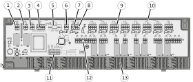
1 – Boiler connection
2 – Pump connection
3 – Protective conductor connection (only for 230 V)
4 – Voltage supply
5 – Fuse
6 – Temperature limiter or dew point sensor
7 – Heating/cooling change-over
8 – Reduction channel, external timer
9 – Thermostat connection
10 – LED
11 – DIP switch “disable cooling”
12 – Connection of actuators
13 – Strain relief

Technical data #

Operating voltage:24 V ±20 %, 50 Hz,
230 V ±10 %, 50 Hz
Power consumption:max. 50 VA
Power consumption (idle):<1 W
Fuse:24 V: T2A / 230 V: T4AH
Connectable room thermostats:max. 8
Connectable actuators, type:A 20×05, AST 20×05, A 40×05, AST 40×05
Connectable actuators:max. 17 actuators
The following applies to other actuators than those mentioned above
Inrush current per actuator:230 V: max. 500 mA
max. permitted nominal load
of the connectable actuators:
24 V: max. 24 W
Pump control switching power:2 A, 200 VA induktiv
Switch-on delay:2 minutes
Follow-up time:2 minutes
Boiler control switching power:2 A, 200 VA induktiv
Switch-on delay:2 minutes
Follow-up time:2 minutes
Pump protection function:3 days / 5 min.
Valve protection function:16 days / 5 min.
Control direction of actuators:NC
Ambient temperature:0 to 50 °C
Storage temperature:-20 to 70 °C
Ambient humidity:80 %, non-condensing
ERP class acc. to EU 811/2013:1=1 %
Contamination degree:2
Rated surge voltage:1500 V
Protection class:24 V: III / 230V: II
Protection type:IP 20
Function:Type 1 / type 1.C
Dimensions (H x L x D):90 x 326,5 x 52 mm
Updated on September 29, 2026
Intended useMontage
Table of Contents
  • Connections and displays 230 V
  • Technical data

© 2024 | 300724

  • Supportrequest
  • Privacy Statement
  • Imprint
  • Supportrequest
  • Privacy Statement
  • Imprint